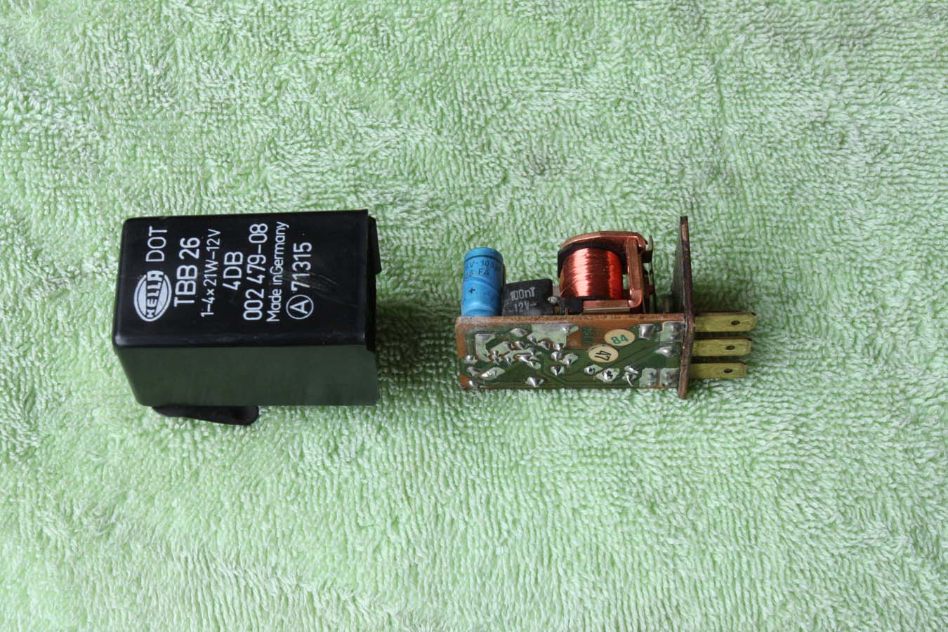
Turn signal flasher evaluation and repair
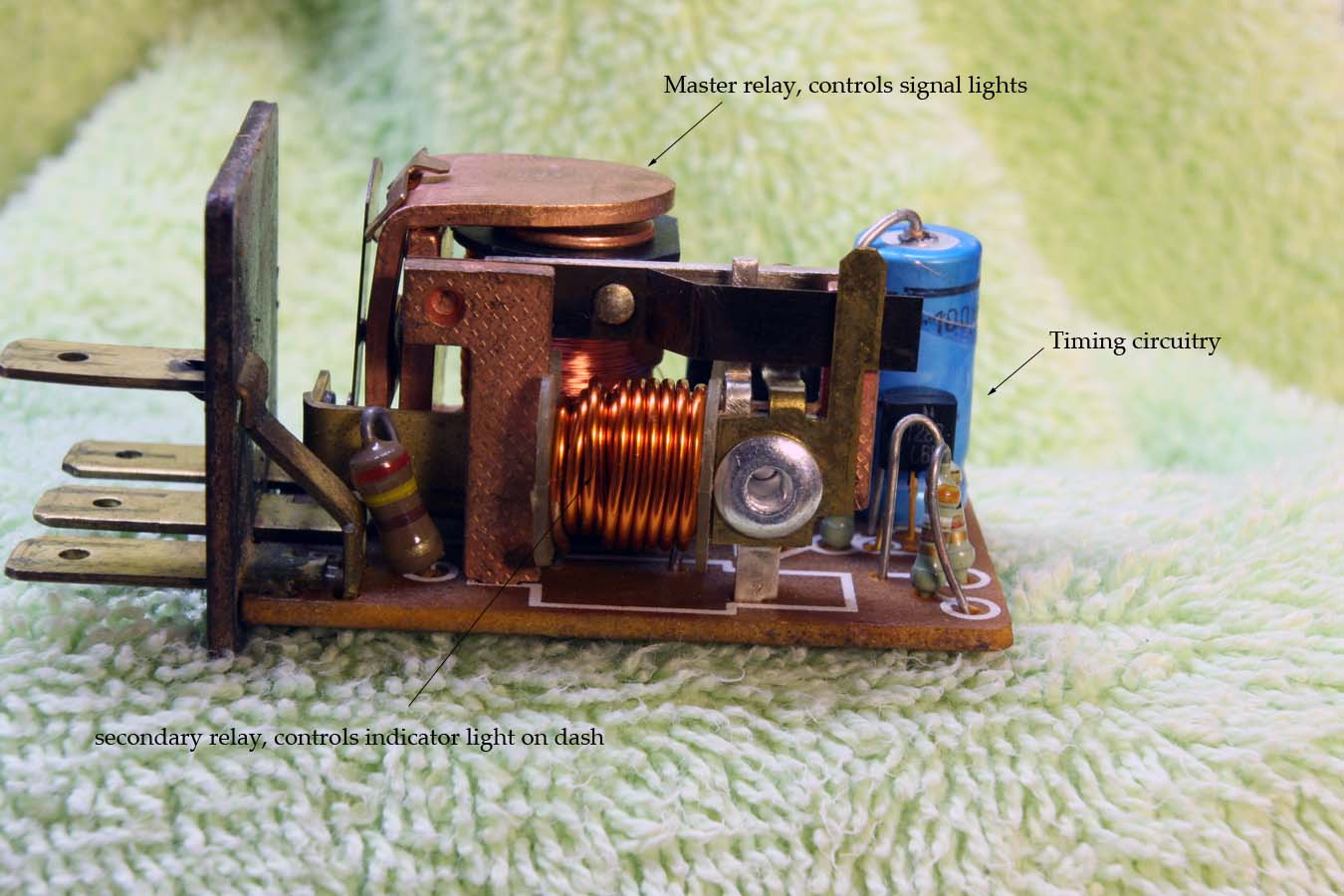
The flasher unit electronics slide out of the housing. There are two relays in the flasher unit. I call them the master and the secondary relays
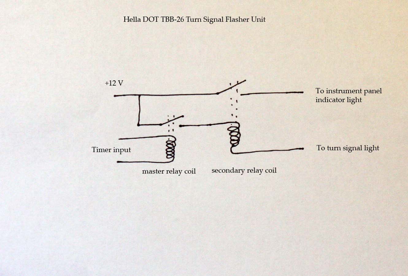
Here is a functional schematic of the flasher unit. When the turn signal is activated with the right hand side thumb switch the transistorized timer circuit in the flasher applies a pulsating signal to the master relay coil. This sends a current through the secondary relay coil as well as lighting up the signal lights on the motorcycle. The secondary relay contacts are connected to the turn signal indicator light on the instrument panel.
If the contacts on the master relay are dirty or oxidized they may pass enough current to (weakly) illuminate the turn signals, but not enough current to close the secondary relay and illuminate the instrument cluster indicator light reliably.
The stack of contacts and insulators on the secondary relay is another trouble spot. If these insulators are degraded they will pass a little bit of current to the indicator bulb even when the turn signal is not actuated. The symptom will be a weakly glowing indicator light all the time.
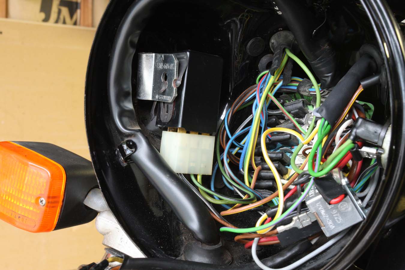
To start the repair, remove the flasher unit from it's bracket on the left side (in this view) of the headlight can.
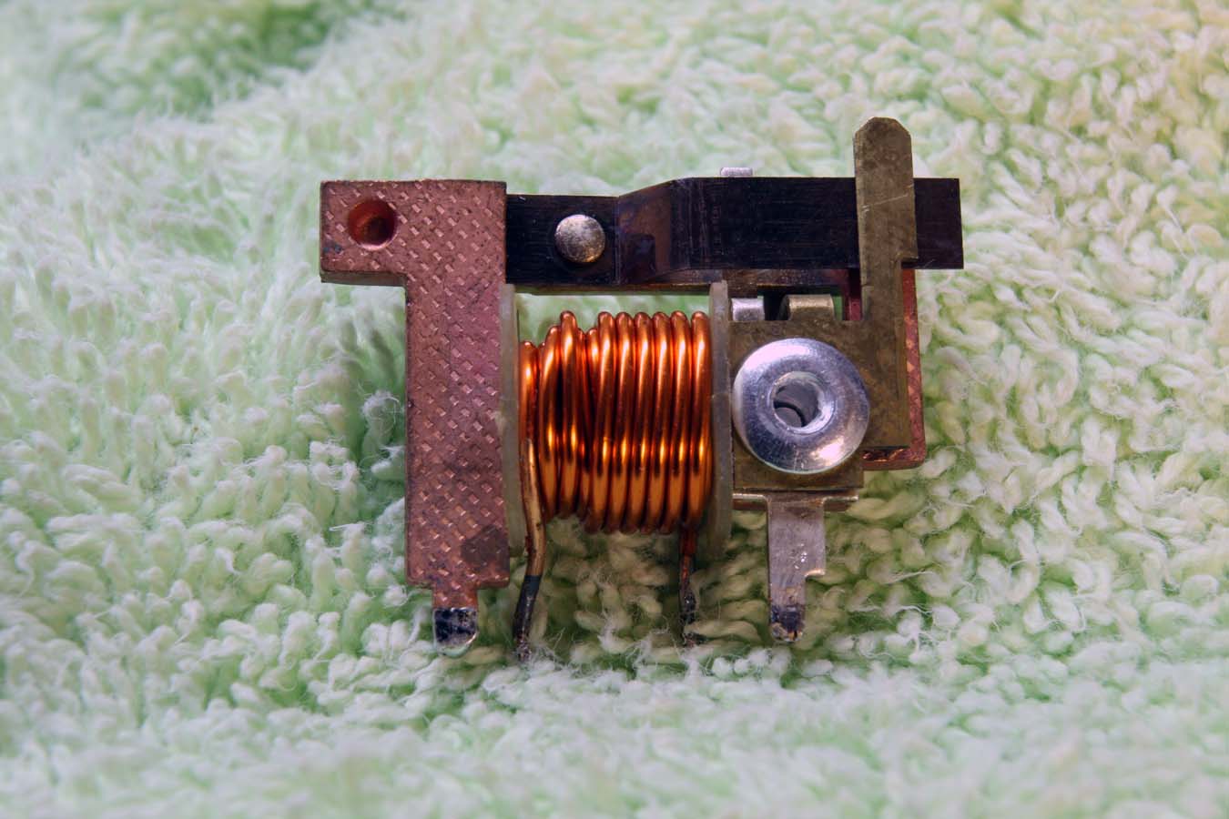
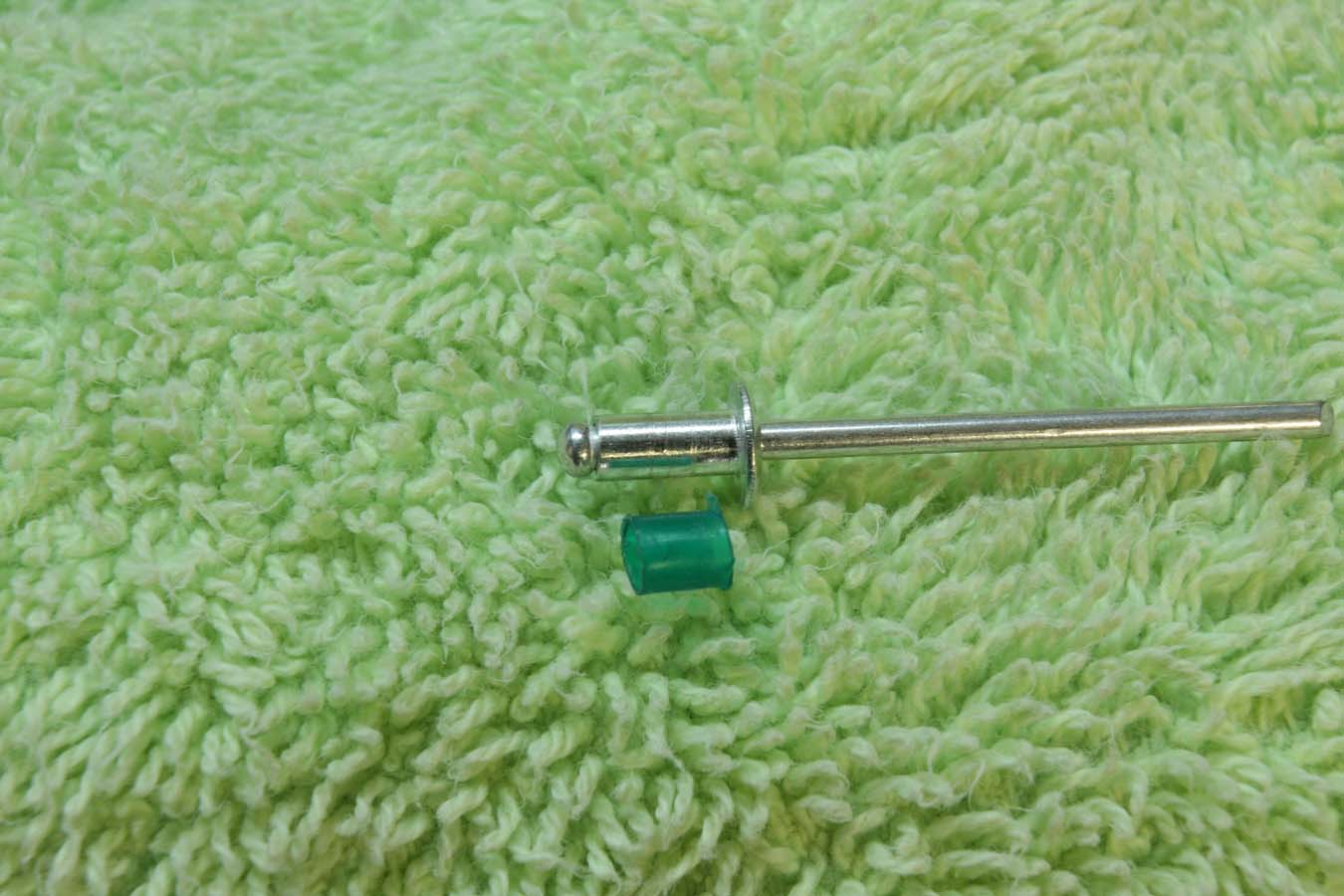
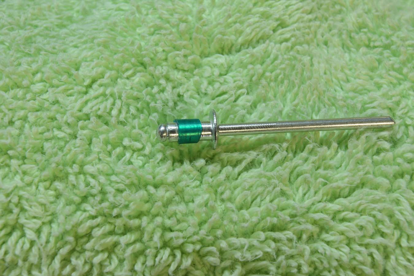
Note the rivet holding the contact and insulators together on the right side of the secondary relay. The original rivet is a hollow rivet, but is not a pop rivet (shown here).
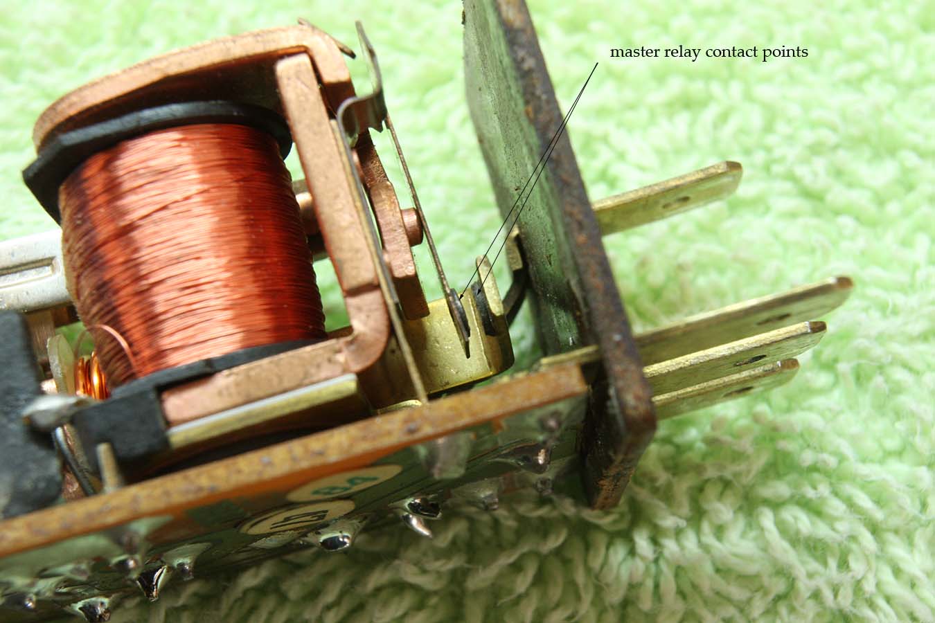
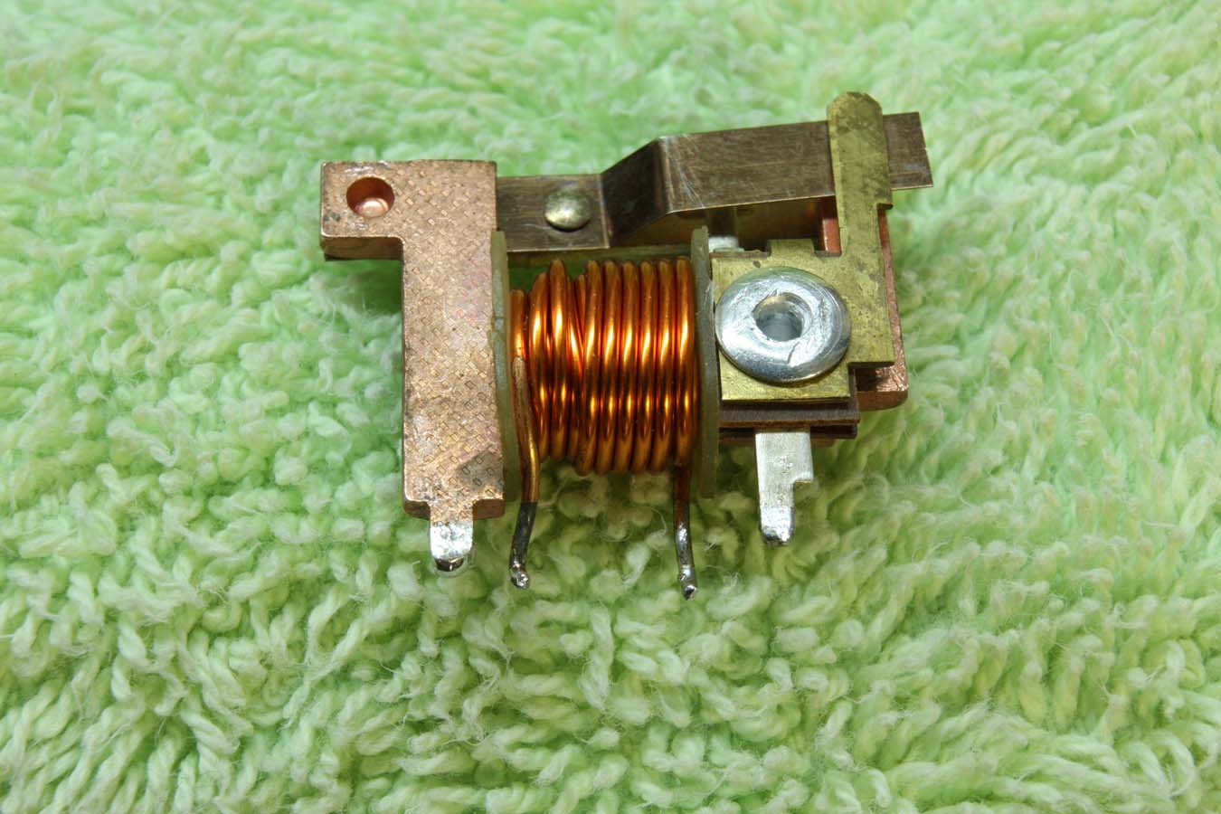
These are the master relay contacts. To polish them up for a low resistance connection just gently slide some 220 sandpaper through the gap while holding the contacts closed. Don't overdo it. This will probably solve the problem of the indicator light not working even though the turn signals themselves are working.
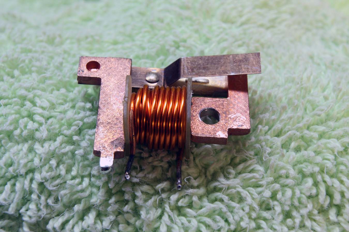
Here the rivet has been drilled out. This hole is 1/8" in diameter, so you will use a 1/8" rivet to eventually reassemble everything.
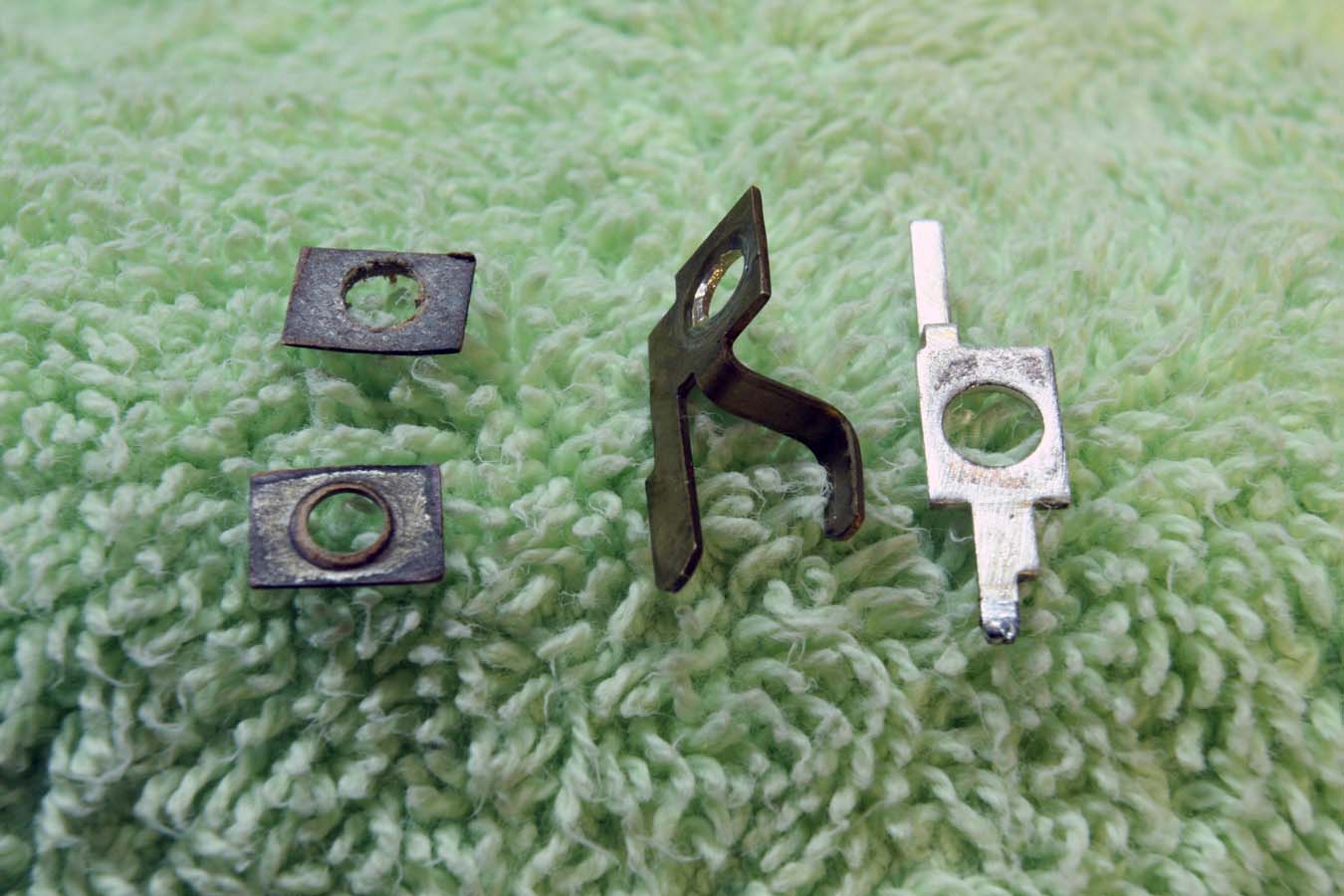
Here are the two insulators (on the left) a support piece, and a silver plated contact. Note how the insulators are pretty shabby looking. They are made from some sort of paper and must have absorbed some water over time because they are no longer good insulators. I was measuring 42 ohms across the contacts on this relay when the relay was open. It should be an infinite resistance in that state.
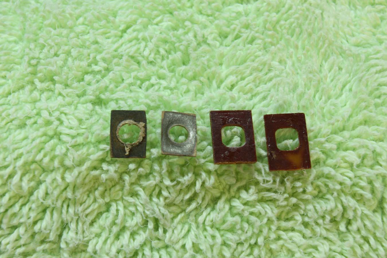
I scavenged some new phenolic insulators from an old phono jack I had laying around. You could probably buy something similar at Radio Shack for a couple of bucks. Worst case, just use some fresh paper or mylar.
The hole in the silver plated contact is larger than 1/8". It is imperative that the rivet does not touch the inner edge of the contact hole when the stack is riveted back together. This can be accomplished by aligning everything carefully. I opted to put a little piece of thin tubing over the rivet as extra insurance against a short circuit.
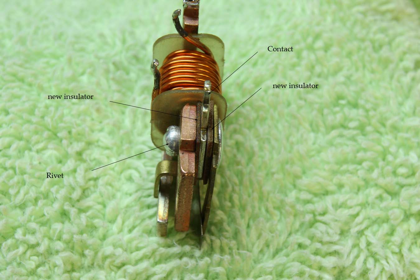
You can see the nicely insulated contact sandwiched between the new phenolic insulators.
A repaired relay, ready to be reinstalled. Fun little project and I saved $65 on a new relay.